
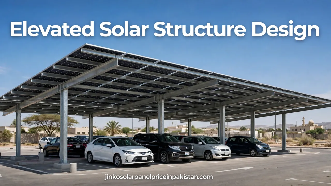
Elevated Solar Structure Design: Height, Span and Load Guide

What is elevated solar structure design? It is the engineering work that decides three things before a single column is cut: how high the panels sit, how far apart the columns can stand, and what loads the whole frame must carry. Get those three decisions right and you have a structure that shelters a car park, a courtyard or a farmyard for decades.
An elevated structure is different from an ordinary rooftop mount: the panels are high enough for people, vehicles or farm work to pass underneath, so the frame is a real building structure, not just racking. Our elevated solar structure guide covers the types — carports, canopies, pergolas and agrivoltaic frames. This article goes one level deeper: the design decisions inside the frame. For the general picture of mounting options, see our solar panel mounting structures guide.
Height: Getting Clearance Right
Height is the first decision because it fixes everything else. The clear height is the distance from the ground to the lowest point of the frame or panels — usually the low edge of the tilted array, not the top of the columns. A common mistake is measuring clearance to the beam and forgetting the tilted panels hang lower on one side. For a carport, start with the tallest vehicle that will ever park there, then add a margin for roof boxes and antennas.
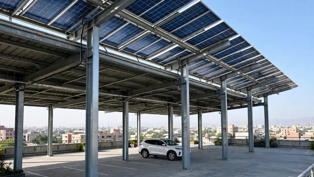
Height also affects how the panels perform. The US Department of Energy notes that mounting structures tilt the array at a fixed angle determined by local latitude, and that tilt sets the height difference between the high and low edges. In Pakistan’s hot climate, height has a second benefit: air circulates freely beneath the panels, carrying heat away instead of letting it build up. But there is a limit: the taller the frame, the longer the columns, the more they flex, and the more wind load they attract. Height should be exactly what the use below requires — no lower, no higher.
Span: How Far Apart Can the Columns Be?
Span is the distance between two columns along a beam, and it decides how open the space below feels. Fewer columns mean easier parking, easier movement of machinery and a cleaner look. But every extra metre of span makes the beam work much harder: bending force grows with the square of the span, so doubling the span roughly quadruples the bending load. That is why long, column-free spans need visibly deeper steel sections.
There are three common ways to get more clear space without simply making the beam bigger. The first is a cantilever: the beam extends past the last column on one side, so the column line can sit at the back of a parking bay while the panels overhang the cars. Cantilever carports keep columns clear of opening doors, but the arm is heavily loaded, and the column and foundation must resist the overturning force. The second is a truss: a triangulated frame spanning much further than a plain beam of the same weight, at the cost of more fabrication work. The third is simply to accept more columns and plan around them, which is often the most economical answer.
Column spacing should follow the layout of the space below. For a carport, columns should land between parking bays, never in the middle of a bay or in the path of a door swing. For a farm frame, columns should sit clear of wheel tracks and turning circles. A layout drawn on paper first will show whether a proposed span is realistic before any steel is ordered. One more span decision is often missed: the purlins and rails between the main beams. Panels rest on rails, rails rest on purlins, and each member has its own span limit, so every member in the load path needs checking, not just the big beams. Our guide to solar mounting rails and clamps explains how rails, clamps and splices work together, and our solar panel row spacing guide covers panel-row spacing and shading.
Load: The Forces Your Structure Must Carry
An elevated structure must carry four kinds of load, and the design has to consider them acting together, not one at a time. Dead load is the permanent weight: the panels, rails, purlins, beams and columns. It is the easiest load to calculate, because every component has a weight on its datasheet. But it grows silently when a design changes — a heavier panel or thicker beam adds dead load the foundations must carry.
Wind load is the governing load for most elevated structures in Pakistan, and the one most often underestimated. A tilted array of panels behaves like a wing: wind passing underneath creates uplift that tries to lift the panels off the frame, wind on top pushes down, and wind from the side creates drag. Because an elevated structure is open on all sides, wind can attack it from any direction, and there is no building to shelter it. Wind pressure grows with the square of wind speed, so a modest increase in speed produces a much larger increase in force. Our solar structure wind load design guide explains uplift, edge effects and why the corners of an array see higher forces than the middle.
Rain adds a third load, and in Pakistan’s monsoon season it is a real one: water running off a large tilted array concentrates at the low edge, and if the drainage is poor it can pond on the frame or cascade onto the space below. A waterproof elevated roof — where the panels themselves form the roof — must also carry standing water if a drain blocks, so drainage is a structural question, not just a comfort one. Finally, there are the loads people forget: maintenance and impact loads. Someone will walk on the frame to clean panels, so it must carry a person’s weight where work happens, and columns in traffic areas need protection — a plinth, a bollard or a guard — or placement where a vehicle cannot reach them.
Foundations: What Holds It All Down
Foundations are the least visible part of an elevated structure and the most expensive to fix after the fact. Their job is twofold: carry the downward weight of the structure and resist uplift — the wind trying to pull the whole frame out of the ground. Uplift is the harder of the two, because a lightweight steel frame with a large panel area can generate far more uplift than its own weight can resist. That is why elevated structures usually need real foundations — reinforced concrete footings, piers or piles — not the shallow pads of a small ground mount.
The right foundation depends on the soil. Firm, stable ground can take a spread footing: a concrete pad wide enough to spread the load and heavy enough to resist uplift. Soft or filled ground may need deeper piers to firmer soil, or driven piles. Expansive clay soils, which swell when wet and shrink when dry, need foundations below the zone of movement, or the frame will tilt seasonally. None of this can be decided from a photograph; it needs a look at the actual ground and, on any structure of significant size, a soil investigation. Two foundation mistakes are common: under-sizing for uplift, and a poor column-to-foundation connection, with anchor bolts too shallow or too close to the concrete edge. Check every anchor bolt position against the drawing before pouring, because moving a bolt afterwards means breaking concrete.
Materials, Bracing and Connections
For elevated structures, the choice is usually between hot-dip galvanised steel and aluminium. Galvanised steel is the default for wide spans and heavy loads: stiff, strong for its cost, and widely fabricated in Pakistan. Its weakness is corrosion at cut ends, welds and bolt holes, where the coating is broken — re-coat those points, or rust starts there. Aluminium is lighter, does not rust, and needs almost no maintenance, suiting coastal areas and smaller residential frames. Its weakness is cost: aluminium deflects more than steel, so long spans need larger sections. Whatever the material, fasteners deserve the same attention: bolts, nuts and washers should be stainless steel or properly coated. The steel frame is also part of the earthing path, so frame, rails and panel frames must be properly bonded — see our earthing and grounding guide and our lightning protection guide.

A frame of only columns and beams is a rectangle, and rectangles collapse sideways unless braced. Bracing — diagonal members between columns, or rigid beam-to-column connections — is what keeps the structure square when wind pushes it sideways or an earthquake shakes it. Cross-bracing is cheap and effective, but it crosses the space below, so place it above the clearance height or along the back line. Connections are where most structural failures start: a beam bolted with too few bolts, bolts in oversized holes, or bolts tightened without a torque specification will work loose under repeated wind loading. Check every connection in the load path as a chain, because the structure fails at its weakest connection, not at its strongest member. Deflection is the quiet failure too: a beam can be strong enough not to break yet sag enough to tilt panels and pond water.
Design Mistakes That Cause Failures
The first mistake is designing from a catalogue instead of from the site: using a supplier’s standard span and height without checking the local wind, soil or use of the space. The second is forgetting the uplift case — a structure fine for the weight of the panels but with no answer for a storm trying to lift it. The third is ignoring the edge and corner zones, where wind forces are highest, and using the same clamp spacing everywhere. The fourth is mixing materials and fasteners without thinking about corrosion. And the fifth is skipping the foundation investigation because the ground looked firm enough. There is also a planning mistake: discovering after building that the structure shades the panels behind it, blocks cleaning access, or sits too close to a boundary. A shading analysis before construction, and a walk around the design imagining the cleaning work, will catch most of these. Our common solar installation mistakes guide covers the wider set of errors across whole projects.
When to Bring In a Structural Engineer
Some elevated structures can be built from a reputable supplier’s engineered kit, with calculations matched to the site. But a structural engineer’s review is essential when the structure is large, shelters people or vehicles, has a long or cantilevered span, sits in a high-wind site, stands on poor or unknown soil, or needs certification for a permit. In Pakistan, where monsoon winds and heavy rain come every year, any carport or canopy over a parking area falls into that category. Ask the engineer for: calculations for the actual site and geometry, not a generic calculation reused from another project; a check of every member and connection; foundation reactions for the footing design; and drawings the fabricator can build from. The cost of that review is a small part of the project, and it is the part that stands between a structure and a storm. If a supplier cannot provide site-specific calculations, get an independent review — and our guide to choosing a solar installer in Pakistan explains how to vet the builders. For background on mounting structures in a complete solar system, see the US Department of Energy’s Solar Photovoltaic System Design Basics.
Frequently Asked Questions (FAQs)
What is elevated solar structure design?
Elevated solar structure design is the engineering work that sets three things before construction: the clear height under the panels, the span between columns, and the loads the frame must carry — its own weight, wind uplift, rain and maintenance loads. The design starts from the use of the space below, not from the panels.
How do you decide the height of an elevated solar structure?
Measure to the lowest panel edge, with the tilt included — not to the top of the columns or the beam. Start with the tallest vehicle or machine that will ever pass underneath, then add a comfortable margin for roof boxes, antennas or anything mounted on top.
How far apart can the columns of an elevated solar structure be?
A longer span means a much heavier beam, because bending force grows with the square of the span. To get more clear space without a bigger beam, designers use cantilevers, trusses, or accept more columns placed on parking-bay lines or clear of machinery tracks.
What is the most important load for an elevated solar structure?
Wind uplift is usually the governing load: a tilted array behaves like a wing, and an open-sided elevated structure can be attacked by wind from any direction. Dead load, rainwater and maintenance loads matter too, and the design must consider all of them acting together.
What kind of foundation does an elevated solar structure need?
It depends on the soil. Firm ground can take a reinforced concrete spread footing, while soft or filled ground may need deeper piers or driven piles. Expansive clay soils need foundations below the zone of seasonal movement. A soil investigation is needed on any structure of significant size.
Is galvanised steel or aluminium better for an elevated solar structure?
Hot-dip galvanised steel is the default for wide spans and heavy loads, but cut ends, welds and bolt holes must be re-coated or rust starts there. Aluminium is lighter and does not rust, suiting coastal areas and smaller frames, but it deflects more, so long spans need larger sections.
When should a structural engineer design an elevated solar structure?
Yes, whenever the structure is large, shelters people or vehicles, has a long or cantilevered span, sits in a high-wind site, stands on poor or unknown soil, or needs certification for a permit. Ask for calculations for the actual site and geometry, a check of every member and connection, and buildable drawings.